Yes, sure! You can buy a Sonoff RF and you are good to go, I guess. But I didn’t and I was not so sure about the no-named RF receiver so I ended thinking about adding my own.
But first things first. The Sonoff is an ESP8266 based smart switch by ITEAD which comes with a custom firmware that communicates with the manufacturer cloud to provide “smart” capabilities like remote switching or scheduling. The cool thing is that it has a line of pins that expose the VCC, GND, RX and TX pins of the ESP8266 and a buttons attached to GPIO0 so very soon it got hacked and there are a number of firmwares already available. I’m not an early adopter and some work has been done and reported by Peter Scargill, Javier or even in instructables.

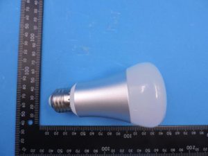
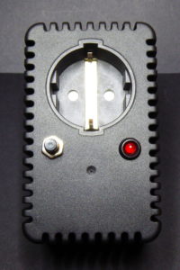
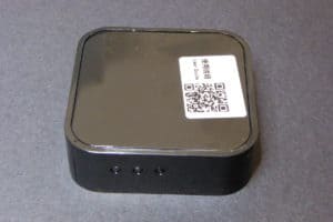
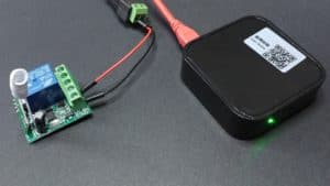
The ITead Sonoff Smart WiFi Switch after a small hack to use the Avidsen RF remote to toggle it
About two months ago I bought 3 Sonoffs TH, the ones ready for mains switching but without RF receiver. When they arrived I reckon I tried ITead eWeLink App for Android but in less that 5 minutes I decided I had nothing to loose getting rid of it and flashing my own firmware.
Truth is that I’m living my own ESP-fever so I immediately plugged it to an FTDI adapter and tried a simple program. Goodbye eWeLink and guarantee voided (does it have any?). When I started figuring out what use could I give them I thought I could embbed them behind the switches in the wall but they are a dime too big and they use simple SPST relays, so no commuting (that’s a fail).
So next thing were lamps and other plugged appliances, starting with a warm lamp in the living room. But this particular lamp was already plugged to a RF switch and switched on/off from a remote. I realized I did not want to loose that. Having to unlock the phone to switch on the light sounded a bit weird. Why didn’t I bought the Sonoff RF instead?
Well, because I was not sure about the RF module it uses. How to handle it from custom code? Will my remote work with it (probably not) or will I have to buy theirs?
Time for a little hacking!
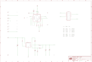
First step was to redo all the work I had already done when I started with these remote. It worked fine with Arduino but not with the Sonoff until I realize the 433MHz receiver I was using required 5V to operate. Mmm… No worries, even thou the ESP8266 works at 3V3 I remembered that in the schema for the Sonoff the AC/DC transformer feeds 5V to an LDO, so I could get the 5V from there.

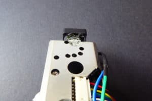
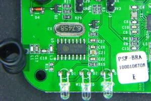
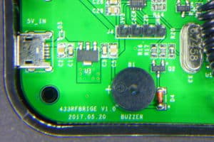
Front view of the Sonoff board with pin descriptions

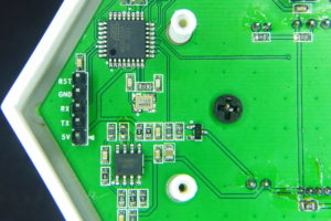
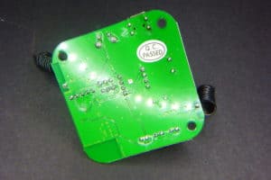
Back view of the Sonoff board with pin descriptions
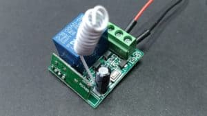
Second problem was where to plug it. The answer was the line of holes where the RF module is in the Sonoff RF. Only two of those pins are tied to the ESP8266, the closest to the relay are GND and 3V3. Could I be so lucky? NO. The receiver I have (the standard RFLink you can find at ebay and such) has 4 pins: GND, DATA, DATA and VCC. Besides, the module just did not fit so close to the relay so the first pin would go in the second hole (the 3V3 hole)… OK, time for the X-Acto knife, the iron and the dremel.

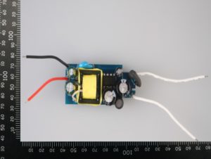
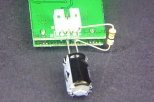
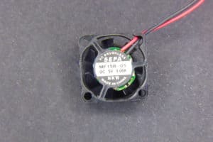
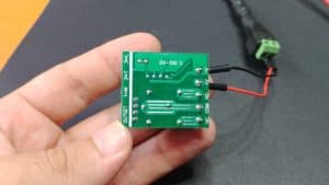
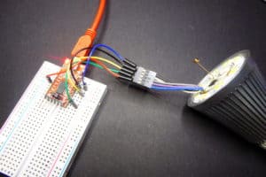
The RF receiver. I removed the black plastic around the pins to solder it closer to the board, otherwise it won’t fit in the case.
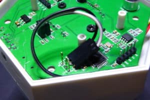
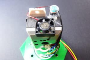
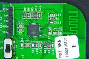
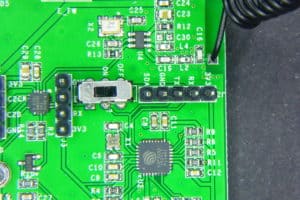
First I cut the traces leading to the 3V3 pin in the RF row of holes (that’s the second hole counting from the relay). There are surface traces on both sides of the board, so I had to cut both and then bridge them together again. Then I soldered the module in the 2nd, 3rd, 4th and 5th holes. I brought GND from the 1st to the 2nd hole, I then connected the DATA pin to the GPIO14 in the perpendicular row of pins through a voltage divider to ground to lower the 5V from the module to 3V3. A 10K and 20K 0805 SMD resistors do the job, but it was really hard to solder them between the pins… Next I soldered the VCC pin of the RF module to a spot in the board I checked was connected to the 5V rail.

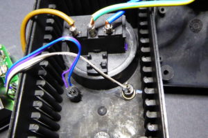
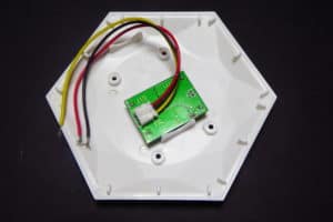
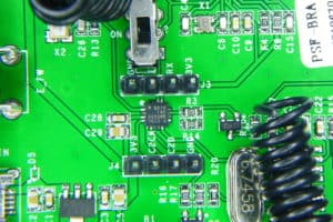
Check the cut just by the LDO, there is another one in the same spot in the other side of the board. But cutting those traces removes power from the ESP8266 so I had to wire it again (it’s the white wire in the right). The other white wire powers the RF module with 5V. You can also see the GND bridge between pins 1 and 2 in the top row and the voltage divider from the DATA line to the GPIO14 and GND pins.

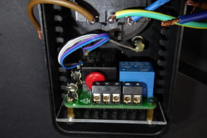
I also had to dremel a bit the case to allow some room for the module
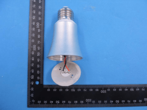
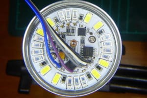
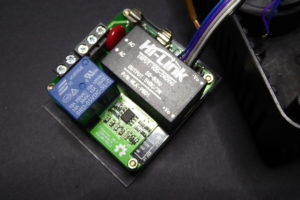
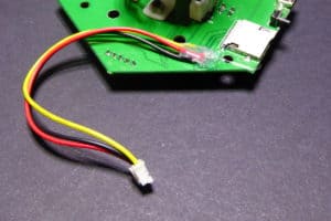
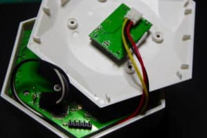
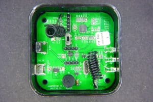
Done. A bit of a mess but it worked!

“My” Sonoff RF
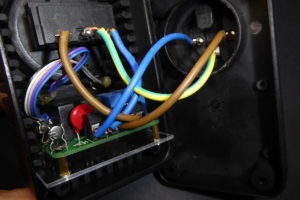
But the maximum distance from the remote to the module was something in the 20cm… until I soldered a 17.3cm wire to the antena hole in the RF module (that 1/4 of a 433MHz wavelength). Now I can be 10 meters away, even with a wall in between and I can still switch it on. And before you say anything: yes, range should be better for a 433MHz module but it’s fine, after all I can still switch it on/off from Australia via the Internet.
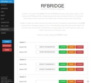
ESPurna Firmware
There are some fine control firmwares out there for the ESP8266. Some of them are generic and let you manage the pins one by one, some of them are more specific for “smart switches” based on the Espressif chip. Most of them have MQTT and Web configuration. Some are small enough so you can flash them Over-the-Air to the 1Mbyte Sonoff. None of them (at least I haven’t found any) have RF capabilities.
So I decided to build my own. After all that’s fun. I’ve named it ESPurna (“espurna” means “spark” in catalan) and it features:
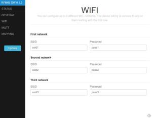
- WebServer for configuration and simple relay toggle
- Flashing firmware Over-The-Air (OTA)
- Up to 3 configurable WIFI networks
- MQTT support with configurable host and topic
- Manual switch ON/OFF with button
- Support for custom RF module (check blog post)
- Visual status of the connection via the LED
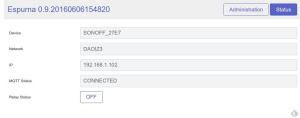
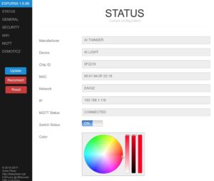
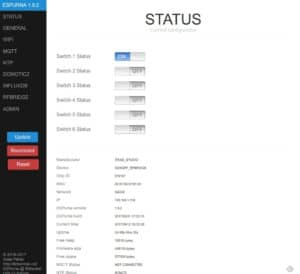
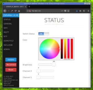
ESPurna status page
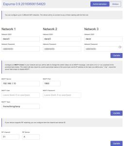
ESPurna administration page
As always, if you are interested in the firmware it is in a espurna repository in bitbucket.
“Wiring” it.
Final step is to “wire” it all together. The Sonoff with the ESPurna firmware connects to my home WiFi and subscribes to a certain MQTT topic. Upon reception it switches on or off the relay depending on the message payload (0 for OFF, 1 for ON, 2 for TOGGLE). Whenever the relay state is changed it also publishes the new state to the same topic (there is code to avoid recursion). So if you change it manually pressing the button or with the RF remote you still have a record of that.
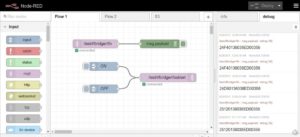
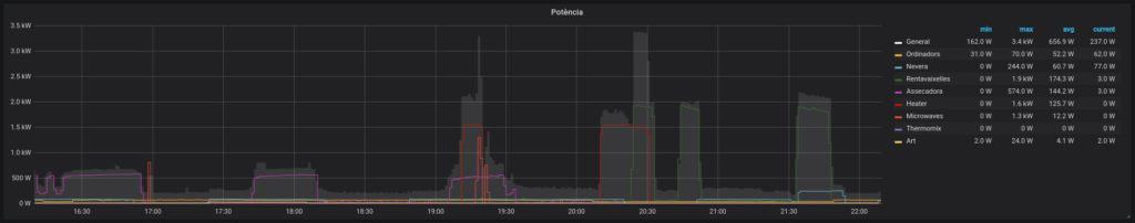
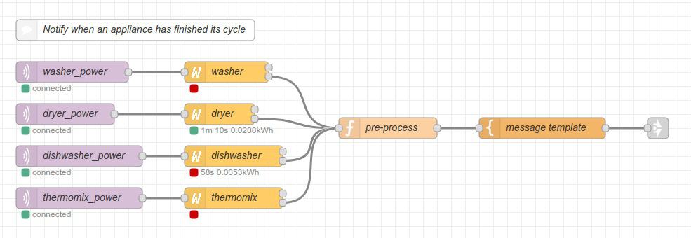
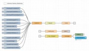
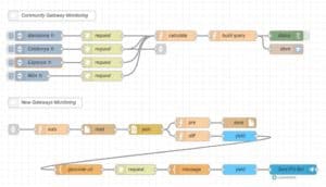
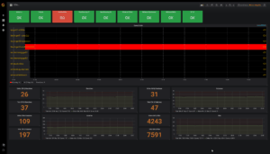
In my home server I have Node-RED running. A few months ago I switched from a bunch of python scripts to Node-RED for message persistence (in MySQL), notifications and to push data to some online services like Xively or TheThings.io.
With MQTT and Node-RED working adding support for Blynk was a piece of cake. In 10 minutes I had a simple dashboard in my phone from where I could switch the lights on and off. In fact, I’ve spent way more time moving around controls in the dashboard canvas trying to make it look cool (I failed).

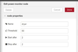
My blynk configuration in Node-RED. So easy!
You know something is well designed when things fit in like magic.
Wow. I feel like I should explain many more things about this project, but there will be a follow up so stay tuned ![]()